So as it turns out, the sizes of print bed available for 3D printers are somewhat limited to ‘standard’ sizes, most of which are bigger than what I intended to go with. 220mm x 220 mm seems to be very common in particular. However, when I measure out what the knock-on effects of a build plate that size are, we’re talking a benchy that could be up to a meter long. That seems like a tad too big.
I did happen to stumble upon a size of print bed that I liked on AliExpress: a 160x160mm print bed from Anet. Knowing I may have to do some minor reinforcement/check-ups on quality I ordered two (just in case one came broken)
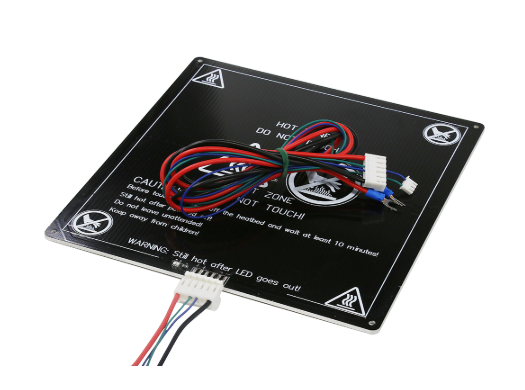
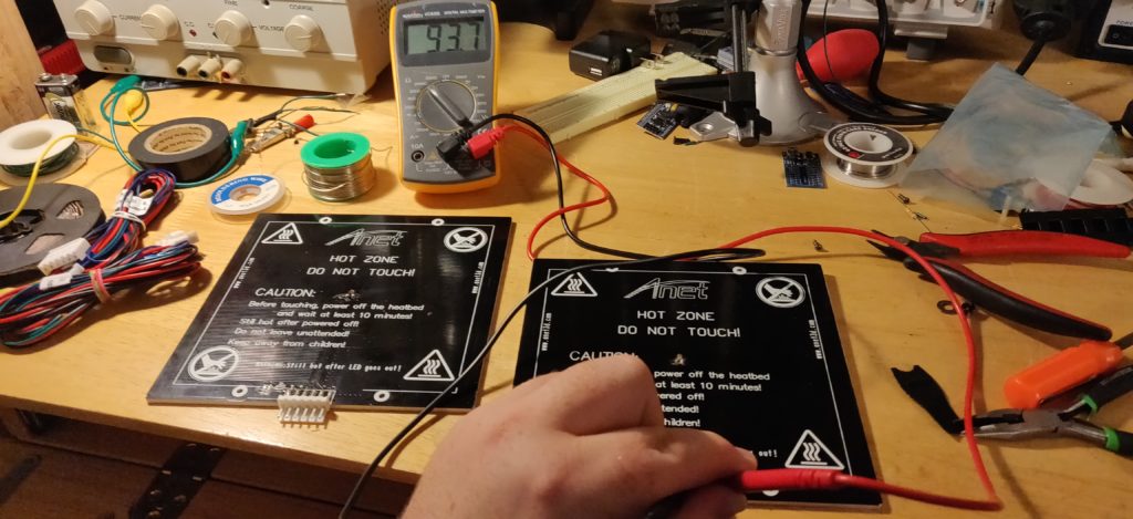
After a few weeks, I had them on my bench ready to be looked over and tested. First step was testing the fragile thermistor used to measure the heated bed temp
According to the RepRap wiki page on thermistors (https://reprap.org/wiki/Thermistor) the most common type used are ‘100kOhm at 25C Negative Temperature Coefficient (NTC)’
What does this mean? Well, let’s break it down.
100kOhms is a resistance value, and we should expect to see this value of resistance between the two wires of the thermocouple at a temperature of 25 Celcius (77 Fahrenheit). The Negative Temperature Coefficient is simply telling us that the resistance will go down as the temperature goes up. A fun way to test this is to touch the thermistor, and as your finger heats up the thermistor, the resistance will slowly decrease. This is also a good way to test that it is somewhat working without passing current through the heated bed.
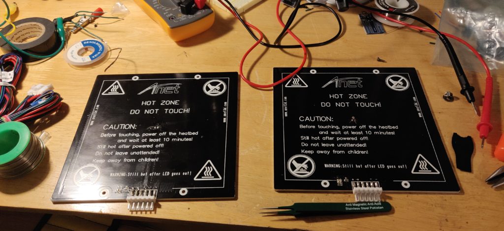
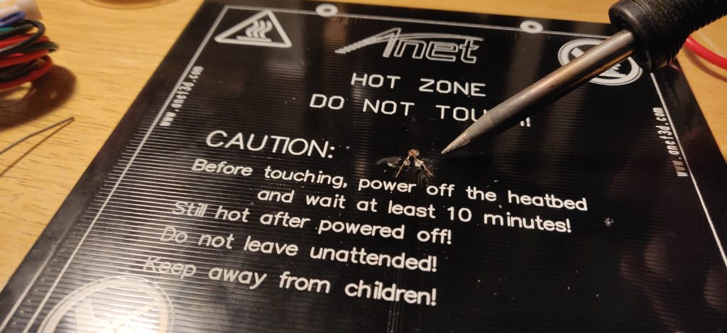
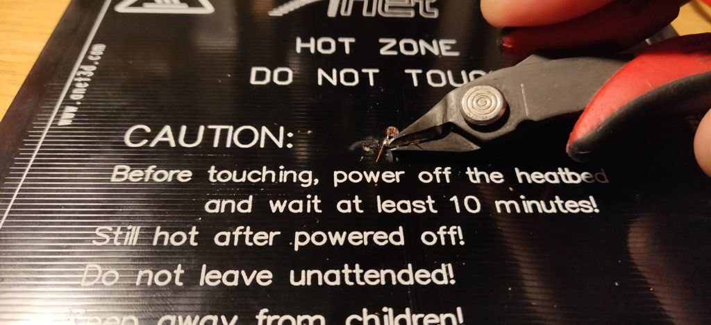
One of the heated beds read 100kOhms across the temperature sensor, meaning it was good to go, and after putting my finger on the sensor and seeing the resistance drop, I was content with passing this one. The second heated bed measured as an open connection, i.e. no current flowing. Didn’t take long to figure out why: one of the leads of the thermistor had sprung loose from the solder pad. Seeing this, I decided to resolder both thermistors on both heatbeds just to be safe

With both beds resoldered, I measured the resistance again, and everything looked as expected with the aformentioned finger test
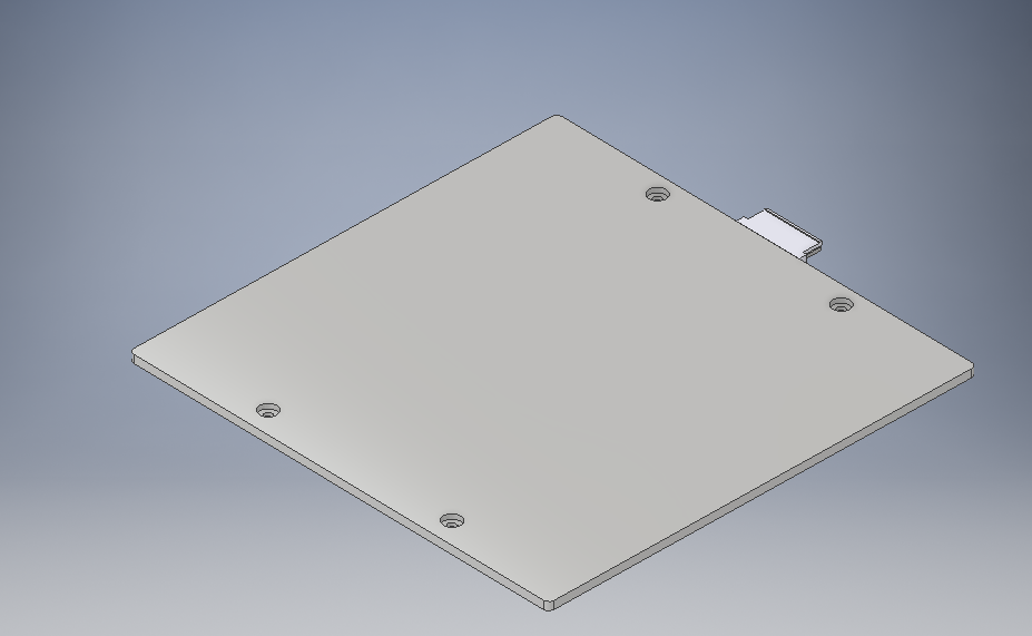
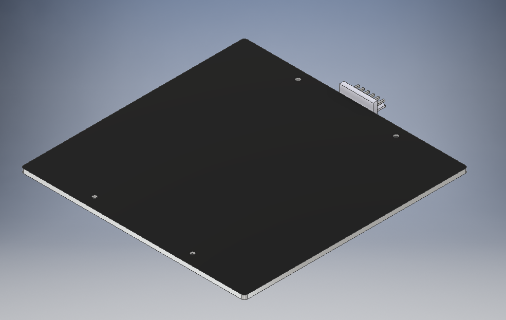
Now that I had a solid idea of the bed size, I could start the designing and 3D modelling of the printer, starting with the bed. Once I know that the dimensions of this model are accurate and I can build parts using it, I’m planning on adding it to GrabCad for other people to use
I had made a few mock-ups of a potential frame, but I decided to start a base model for the frame after having the print bed dimensions so as to build the frame around it. Mileage on this technique may vary, and I had to do a lot of work over, but I did manage to get a sense of scale for what the printer would be looking like. In a helpful coincidence, the frame designs I had been thinking about got me very close to a uniform scale of 10X the size of your average Benchy. That gets us a Benchybot that is roughly 650mm long, 360mm wide, and 550mm tall, which, although being an extremely large Benchy, will still fit on a table with ease.
Part 2 will cover the basic sizing of the print frame, and figuring out how to assemble some of the first structural components of the design.
You can find Part 0 here: https://happylittlepcbs.net/benchybot-part-0-intro/